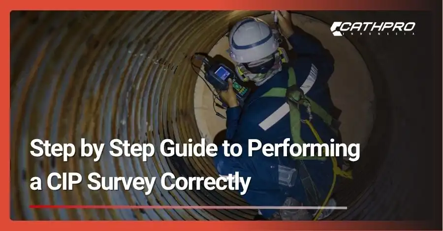
Pipeline corrosion silently threatens billions of dollars in infrastructure every year. What if one critical survey could prevent catastrophic failures and save your organization millions? Welcome to the world of Close Interval Potential (CIP) surveys – your frontline defense against pipeline deterioration.
A CIP survey is a comprehensive electrochemical assessment that measures the effectiveness of cathodic protection systems along buried pipelines. This step-by-step guide to performing a CIP survey correctly will equip you with the knowledge to conduct thorough, accurate assessments that ensure pipeline integrity and regulatory compliance.
Whether you’re a seasoned pipeline engineer or new to corrosion protection, mastering the CIP survey process is essential for maintaining safe, reliable pipeline operations. Let’s dive into the systematic approach that transforms complex electrochemical measurements into actionable pipeline integrity data.
The Foundation – Pre-Survey Planning & Preparation
Step 1: Define the Scope and Objectives
Success in CIP surveying begins with crystal-clear objectives. Start by identifying the specific pipeline segment requiring assessment – this could range from a few hundred meters to several kilometers depending on your project scope.
Determine your survey purpose early. Are you commissioning a new cathodic protection system? Conducting annual compliance inspections? Investigating potential corrosion issues? Each objective demands slightly different approaches and measurement criteria.
Document your scope boundaries precisely, including start and end points, any branch connections, and special considerations like river crossings or road intersections. This clarity prevents costly resurveys and ensures comprehensive coverage.
Step 2: Assemble Your Team and Equipment
Professional CIP surveys require coordinated teamwork. Assign clear roles: the lead surveyor handles measurements and data interpretation, while the data logger manages equipment and records observations. Include a safety coordinator for complex routes.
Essential equipment includes a calibrated data logger, GPS unit, copper-copper sulfate reference electrode, survey cables, and current interrupter access. Don’t forget backup batteries, spare cables, and weatherproof data storage.
Equipment calibration is non-negotiable. Verify your reference electrode against known standards, check data logger accuracy, and ensure GPS functionality. A pre-survey equipment checklist prevents field delays and measurement errors.
Step 3: Secure the Route and Ensure Safety
Route preparation involves multiple stakeholders. Contact landowners for access permissions, coordinate with local authorities for road crossings, and notify relevant utility companies about your survey activities.
Develop comprehensive safety protocols addressing specific route hazards. Live pipeline considerations, traffic management, weather conditions, and emergency procedures must be clearly defined and communicated to all team members.
Risk assessment should cover both immediate hazards and long-term exposure risks. High-traffic areas may require traffic control measures, while remote locations need communication backup plans and emergency contact procedures.
Execution – The Survey Procedure
Step 4: Establish the Test Point and GPS Reference
Begin your CIP survey methodology by establishing a precise starting reference point. Connect to the nearest cathodic protection test station or create a temporary reference point with known GPS coordinates.
GPS accuracy directly impacts data quality and future survey repeatability. Use differential GPS when available, and record coordinates in the same datum system used for pipeline mapping. Mark your starting point clearly for future reference.
Verify your reference electrode connection and ensure stable baseline readings before proceeding. Unstable initial readings often indicate equipment issues or poor electrode contact that must be resolved immediately.
Step 5: Laying Out the Survey Cable
Proper cable placement follows the pipeline route as closely as possible while maintaining safe distances from other utilities and traffic. Use pipeline markers, previous survey data, and utility locating services to confirm routing.
Navigate obstacles systematically. Road crossings may require directional drilling data for accurate cable placement, while fence lines need landowner coordination and gate access arrangements. Document any deviations from the intended route.
Maintain consistent cable spacing – typically 2.5 to 5 feet intervals depending on survey objectives and terrain conditions. Closer spacing provides higher resolution but increases survey time and data volume.
Step 6: Taking Potential Measurements
CIP survey measurements capture both “ON” and “OFF” potential readings. ON potentials measure the combined effect of cathodic protection current and natural corrosion potentials, while OFF potentials eliminate IR drop effects for true pipe-to-soil potential assessment.
Use your current interrupter to cycle the cathodic protection system systematically. Standard cycling involves 3.3-second ON periods followed by 1.2-second OFF periods, allowing adequate time for polarization decay.
Maintain consistent reference electrode contact with soil throughout measurements. Poor electrode contact creates measurement errors that compromise survey validity. Use a small amount of bentonite clay if necessary to improve soil contact.
Step 7: Data Recording and Quality Control
Modern data loggers automate most recording functions, but active monitoring prevents costly errors. Watch for consistent GPS tracking, stable electrode readings, and proper current interrupter synchronization throughout the survey.
Implement real-time quality control by spot-checking readings against expected values. Sudden potential shifts may indicate measurement errors, cable damage, or genuine pipeline conditions requiring immediate attention.
Document environmental conditions, landmark references, and any anomalies encountered. These notes prove invaluable during data analysis and help explain unexpected measurement patterns.
The Aftermath – Data Analysis & Reporting
Step 8: Uploading and Processing the Data
Transfer survey data promptly to prevent loss and begin preliminary analysis. Most CIP survey software packages import data directly from logger memory cards and automatically generate location-corrected potential profiles.
Generate preliminary graphs immediately to identify obvious data quality issues. Missing GPS coordinates, erratic potential readings, or synchronization problems are easier to correct shortly after survey completion.
Back up raw data files in multiple locations before beginning analysis. Original survey data represents significant investment and may be required for regulatory submissions or legal proceedings.
Step 9: Interpreting the CIP Survey Results
CIP survey interpretation requires understanding electrochemical principles and pipeline protection criteria. OFF potentials more negative than -850 mV (Cu/CuSO4) typically indicate adequate cathodic protection, while less negative values suggest potential corrosion activity.
Look for characteristic patterns: gradually declining potentials may indicate current distribution issues, while sharp potential shifts often reveal coating defects or pipeline features. Areas showing less negative OFF potentials require further investigation.
Compare ON and OFF potential differences to assess IR drop effects. Large differences suggest high soil resistivity or inadequate current distribution, both requiring system optimization.
Step 10: Creating a Comprehensive Report
Professional CIP survey reports follow standardized formats including executive summary, methodology description, results presentation, and recommendations. Include all relevant graphs, maps, and supporting documentation.
Visual presentation enhances report effectiveness. Color-coded potential profiles clearly highlight areas meeting or failing protection criteria, while overlay maps show geographic relationships between measurements and pipeline features.
Provide specific recommendations based on survey findings. Areas requiring immediate attention, suggested system modifications, and future monitoring requirements give clients actionable guidance for maintaining pipeline integrity.
Conclusion
This comprehensive step-by-step guide to performing a CIP survey correctly transforms complex electrochemical assessments into manageable, systematic procedures. From initial planning through final reporting, each step builds upon the previous to ensure accurate, reliable pipeline integrity evaluation.
Remember that proper CIP survey execution requires both technical competence and attention to detail. The systematic approach outlined here minimizes errors while maximizing data quality and survey efficiency.
Ready to implement these CIP survey best practices? Start with thorough pre-survey planning, invest in quality equipment and training, and always prioritize safety throughout the process. For complex pipeline systems or critical infrastructure, consider partnering with experienced cathodic protection professionals to ensure optimal results and regulatory compliance.
Ensure Pipeline Integrity with Cathpro Indonesia
Don’t leave your pipeline protection to chance. With years of proven expertise in cathodic protection and CIP surveys, Cathpro Indonesia helps you achieve accurate assessments, reliable data, and full compliance with industry standards.
👉 Partner with our experienced team today to safeguard your critical infrastructure with confidence.


